Make more fluid with less gas
Written by Kenneth Estrada, Concho Resources Inc., and Jay Miller, independent consulstant, with the collaboration of Damien Leonard, founder of Increase Well Production Limited.
New gas lift valve spacing design used in unconventional wells
In a historical discussion of different gas-lift design methods, the theory behind them and considering current practices, one running theme tends to rear its head repeatedly: valve spacing. In the existing plays being sought after in the Permian Basin and elsewhere, a new design method may be more beneficial. In early 2019, Concho Resources and Production Lift Companies ran a new gas-lift design method in two unconventional wells in the Permian Basin.
This new method is designed to exploit the initial high bottomhole pressure (BHP) in unconventional wells to produce higher rates that, before now, were only possible with an electric submersible pump. Getting through the highest volumes of the earliest production and continuing to be an effective form of artificial lift into the well’s later years, this life-of-well design will also follow the well’s decline and efficiently produce the well at lower rates. When completed correctly, the well can be switched to plunger assisted gas lift, plunger lift or gas-assisted plunger lift without the need for rig intervention. Thus, there is no tubing pull required.
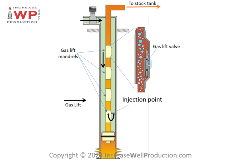
Origin of the 500 ft minimum gas lift mandrel spacing
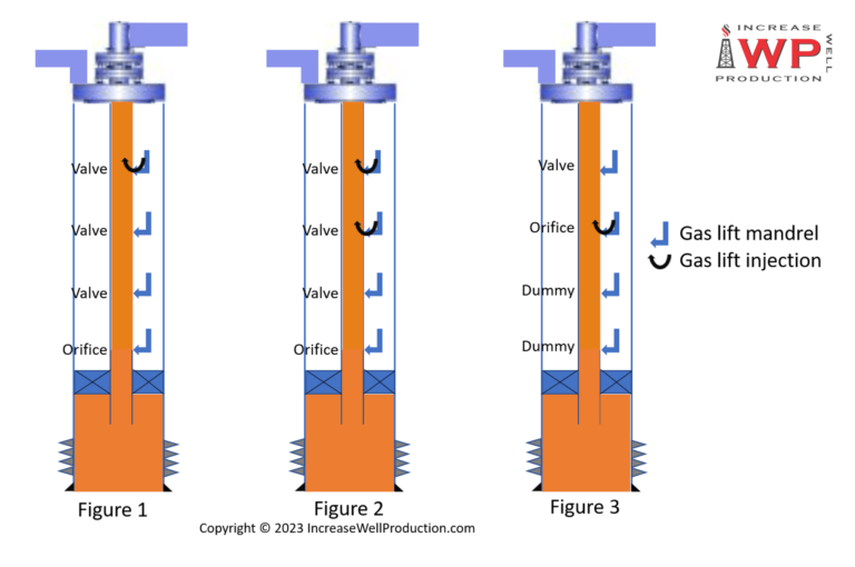
The Austin Chalk horizontal wells of South Texas and Louisiana changed everything in the gas-lift world. The traditional gas-lift design methods used to design vertical wells would not work for horizontal wells. The best gas-lift design method for horizontal Austin Chalk wells is to run unloading valves until reaching a minimum spacing of 500-ft (Figure 1) and then continue the 500-ft spacing down to the packer. The 500-ft spacing is an arbitrary spacing that is not based on engineering principles. A group of gas-lift professionals came up with 500-ft spacing by trial and error in the late 1980s while writing one of the first gas lift design program for a major Gas Lift equipment supplier. Since it worked in the Austin Chalk horizontal wells, this method was thought to be best for all horizontal wells and adopted by the industry at that time as a “best practice” and has remained the standard today.

The challenge of gas lift production in horizontal wells
The oil and gas industry naturally had to adjust from mostly vertical wells to the up-and-coming horizontal wells in the 1980s. Many adaptations happened to make downhole tools work horizontally that were designed to work vertically, and those adaptations are still happening today. From completion techniques to artificial lift methods, constant revisions and iterations of tools and designs already in use are taking place.
Following suit, the gas-lift industry had to adapt too. At the time, most gas-lift designs were still being done by hand, and the Austin Chalk horizontal wells performed differently than the vertical wells of yesteryear. They headed terribly and no longer had predictable inflow performance. They made lots of gas, they slugged, made fines and lent themselves to gas lift very well given gas lift thrives in gassy wells producing solids. Many things were tried to lift these wells. Gas-lift valves were run around the corner into the open hole. Dip tubes also were used in an attempt to lower the pressure and make more fluid. Alas, this did not help to make more fluid. Those early attempts to lift these wells worked but were very limited in what they could produce. The next adaptation for horizontal gas lift that was attempted was the bracketed gas-lift design.
Featured courses

Bracketed gas lift designs
It was around this time when desktop computers became available and there were Nodal analysis programs around, but they were DOS programs for mainframe computers. One was called GLOP and one was called GLAD. A more modern program that would run on a desktop computer was coming.
The first program written was still a windows GUI program that allowed to do a complex Nodal based gas lift design. It was the first program written that defaulted to the 500-ft spacing operating bracket for gas lift valves. As those programs were updated throughout the years, the 500-ft spacing was kept. All of the gas lift companies and gas lift design programs operating today adopted the 500-ft bracket spacing. That’s why you see it today on most designs. The bracketed design method works but is not as efficient as other methods being tested today.
The gas lift companies in business today mostly came from one company. In the 80’s, McMurry Oil Tools was the industry leader in the gas lift business. Other prominent gas lift companies at that time were: Macco, Schlumberger, Camco and Daniel Oil Tools. In the mid to late 80’s, Masco bought Macco, McMurry and Daniel. All three were combined to form Weatherford Artificial Lift. Over the years, people left these industry leaders and formed other gas lift companies like International Lift Systems, Flowco, Epic and Liberty Lift. The same gas lift design program was used as model for all the gas lift design programs these companies bought or wrote. They all copied the 500-ft spacing. That is why all gas lift designs seem to look the same.
Bracketing the valves is a practice where gas-lift valves are run on the tubing:
- at an equal spacing
- respecting a minimum mandrel spacing
- below the depth where nodal analysis shows to be the deepest possible point to inject gas (while respecting the minimum mandrel spacing).
This method was typically used in high-rate vertical wells where the productivity index is known and relatively constant.
Bracketing eventually evolved into a standard practice in horizontal wells, because little reservoir information was known. An equal spacing (like 500-ft) allows the lift system to remain in the hole and follow well decline without intervention on the well.
Early time production potential hindered by 500 ft minimum gas lift mandrel spacing
Recent flowing bottom hole pressure surveys have shown that the nodal-based unloading sections of the Austin Chalk designs, with the 500-ft brackets, are actually slowing the unloading process and causing problems in unconventional horizontal wells. The unloading valves are routinely spaced too wide, which retards the transfer to the next gas-lift valve and inhibits the unloading process, making the possible drawdown of the formation lessened and hindering early time production. The valves will tend to chatter (open and close very quickly) when they cannot transfer to the next valve and may cause undue fatigue in the bellows. Chattering causes the valves to leak and/or fail in addition to hurting well performance.
Nodal-based gas lift designs
Nodal-based gas-lift designs have previously worked great for traditional vertical wells where nodal analysis is used to create an inflow performance relationship curve to predict well performance and determine the best depth, or point of injection, at which to lift fluid from within a well. Conventional vertical wells typically have a constant BHP, a consistent drive mechanism and support a relatively constant productivity index. In wells like these, the use of nodal analysis to predict well performance and aid in the gas lift design is very common and unmistakably useful. Unfortunately, nodal-based well analysis is not a valid method to predict an unconventional well’s performance over the long term. This method measures a fixed performance point, but today’s shale wells cannot be gauged by this metric. With such rapid decline rates in production, dropping the productivity index and reductions in BHP, unconventional wells change too quickly for nodal to give an accurate answer to the long-term performance model.
Unconventional GLR-based gas lift design for high liquid rate wells
The new High Rate Unconventional GLR-Based Gas Lift Method can produce higher rates than typical 500-ft bracketed designs and transition from top valve to bottom with ease, using fewer valves.
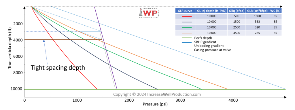
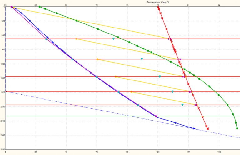
The design works best when the gas-liquid ratio (GLR), static BHP (SBHP), flowing BHP and Productivity Index are known. With that information, the point of injection can be pinpointed and will determine where the bracketed valves need to start. If the SBHP is known, or merely estimated, and nothing else is available, then the GLR-based method can indeed be used, although it will require some guesswork by the gas lift designer. The GLR-based design starts by first plotting the SBHP on the graph and adding a family of GLR curves (Figure 2). These curves will become handy to evaluate the different rate that can be achieved with the gas lift design.

Figure 2: Gas lift design preparation plots with multiple liquid rate and GLR curves
The tight spacing is made around the highest rate achievable with the given SBHP and GLR (Figure 3). This is an estimated depth and becomes more accurate as more offset well data are acquired and utilized.
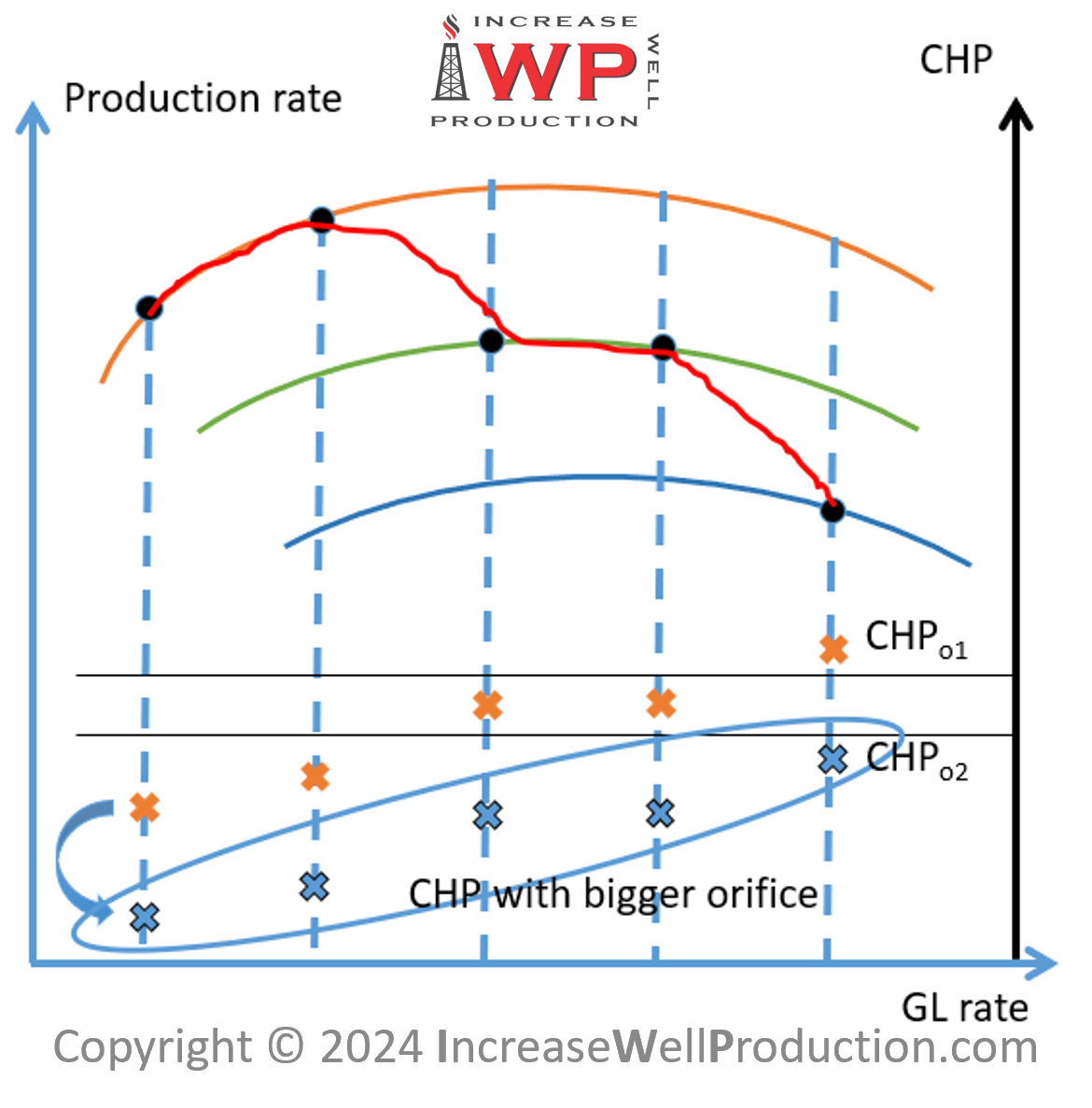
Gas lift multipoint injection aka gas lift multipointing
Multipoint injection is considered a bad thing with respect to traditional single-point injection gas lift. Gas lift valves are primarily a flow control device and, typically, injecting through one at a time is normally desired to get the best well performance.
High-rate gas lift is a nodal-based gas-lift design method introduced in the mid-1980s where gas-lift valves are placed in proximity in the tubing string, sometimes as closely as 30 m (100 ft) apart. Doing so will purposefully cause them to interfere with each other and ultimately keep the valves open. Interference of two valves with one another is known as multipointing. The intention of purposely multipointing is to assist in the injection of higher volumes of gas into the same area while retaining the flexibility of certain valve and port sizes. Shifting from upper to lower valves, the reservoir no longer gives up fluid at the same rate it did initially, thus it’s easier to keep up with unloading and allows transition more slowly from one valve to the next. This provides for the ability to adjust the antiquated 500-ft spacing that was arbitrary to begin with and adopt a more modern, tailored and suitable lower valve spacing for unconventional horizontal wells.
Injecting gas lift across multiple gas lift valves to allow more gas injection
Multiple valves open within that close of a proximity allows more gas to be injected easier, introduces more gas in one section of the well, will lighten the fluid column and produce more fluid. This allows the natural reservoir pressure of the formation to become more effective in overcoming the hydrostatic head of the fluid column and push the fluid to the surface. Differential pressure is needed to inject gas through the valve from the higher pressured casing to the lower pressured tubing. A 1-in. port valve is used to inject hundreds of thousands cubic feet of gas per day into the tubing string and, given ample clearances in the production casing, a 1.5-in. gas-lift valve is typically used too.
“Multipointing is an inefficient use of lift gas and should be eliminated when possible,” said Kenneth Decker of Decker Technology. The achievement of this goal is based on the assumption that the gas lift valve has the capacity to flow the required amount of gas to achieve the desired GLR given the current pressure conditions. When lifting from unloading gas lift valves, as is the case when using gas lift early in the life of unconventional wells, due to the gas lift valve throttling effect and the limited differential pressure available the flow performance of the gas lift valve is much less than an orifice and, consequently, a single gas lift valve is not capable of flowing the volume of gas needed to achieve single-point injection.
This is particularly true for 1-in. valves and less so for 1.5-in. valves, as the production pressure effect factor (PPEF) is lower in 1.5-in gas lift valves than in 1-in gas lift valves, hence 1.5-in gas lift valves are less subject to throttling effect. Trying to achieve single-point injection in an unconventional well while the reservoir pressure is declining rapidly should not be a design goal, nor should time and expense be put forth to remediate multipointing at this time. When the reservoir pressure has declined to a fairly stable value, engineering efforts can be initiated to achieve single-point injection.
Featured courses

1-in gas lift valves limit injection gas rate
These case study wells were completed with 5.5-in. production casing. As a result, 1.5-in. gas-lift valves cannot be used because that size of gas lift valve requires a larger outer diameter mandrel and will not fit into 5.5- in. production casing when run on 2 7⁄8-in. production tubing. These unconventional wells require the use of 1-in. gas lift valves in a 2 7⁄8-in. tubing mandrel. The valve performance with a 1-in. gas-lift valve will not allow an operator to use ports big enough to inject the gas volumes needed to produce higher rates in these wells.
Spacing several smaller port valves (smaller port gas lift valves will be less subject to throttling than larger port ones) within proximity, multipoint injection will occur and allow an operator to inject enough gas in one area of the well to produce the highest rates possible at depth in unconventional wells. Close by valves should be designed to open and close at very similar casing pressure, hence acting as one much larger valve rather than 3 separate ones. By spacing these unloading valves so closely, the opportunity to transfer down through the valves is sped up; thus, getting to lower valves sooner is possible. This theory takes advantage of the early time production and productivity index of a newer shale well, where production declines are known to be more severe.
One could argue that an alternative method could be to have a single valve equipped with an orifice and plan to replace that orifice early in the life of the well. As this valve will be shallow, slick line intervention remains possible due to the low deviation in that portion of the well. This would however mean working with side pocket mandrels which will make the conversion to plunger lift more complicated later in the well’s life. Hence there is value in the method described in this paper when using conventional gas lift mandrels.
Extended mandrel spacing for later life of the well
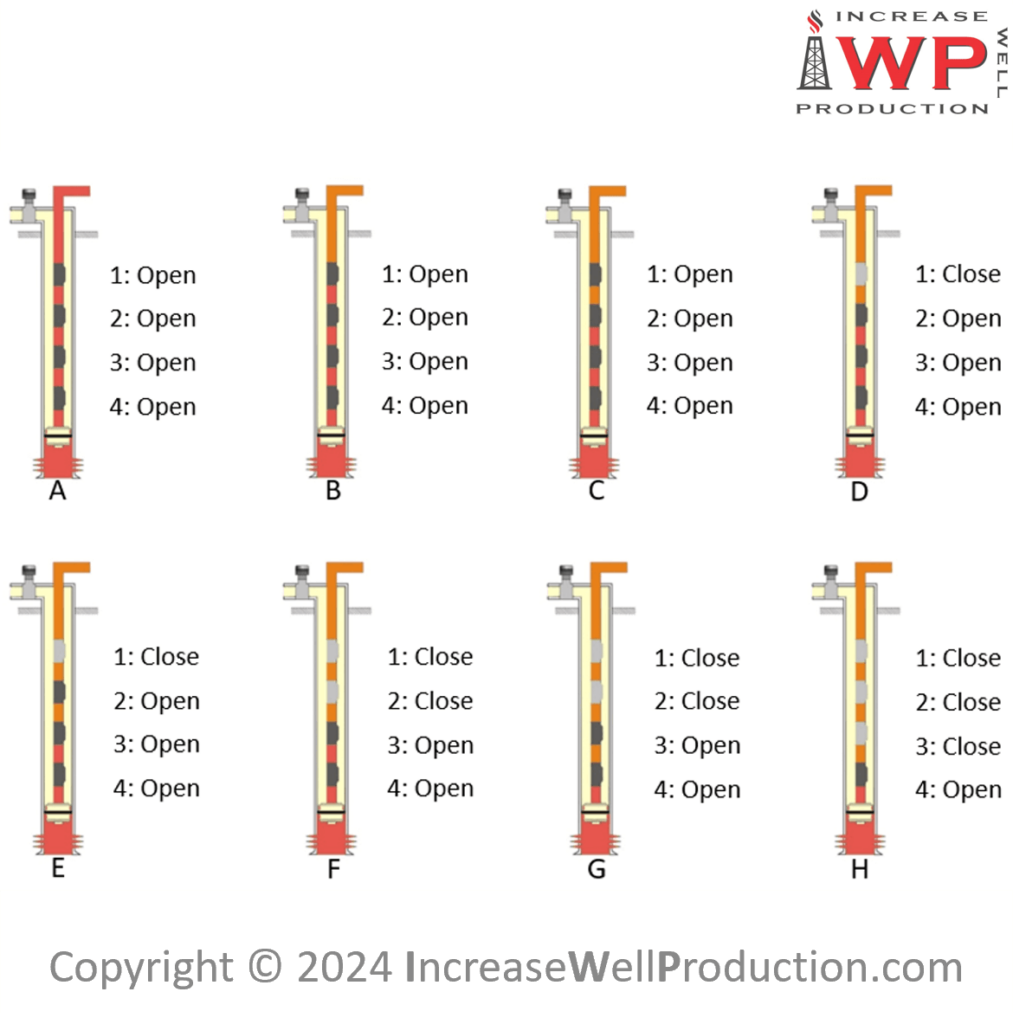
The High Rate Unconventional GLR-Based Gas Lift Method (Figure 4) has plenty of merit in today’s unconventional shale plays. The transition from upper valves to lower valves can be greatly expedited on these unconventional wells by closely spacing the higher valves. This allows the rapid unloading process to create a higher rate in the critical early time of production. It is at this point where the highest natural reservoir pressure is helping the lifting process, and the productivity index will be the greatest in the well’s life. The opposite can be said when getting down to the valves in the lower portion of the well.

Figure 4: High Rate Unconventional GLR-Based Gas Lift Design example
The wider and wider spacing located where most would begin to bracket is primarily due to the tight nature of the shales that are dealt with in the Permian basin. The porosity and permeability are such that productivity indexes within a year are not uncommonly below 1 bfpd/psi, or even 0.5 bfpd/psi. The deliverability of the reservoir is not high enough at these points to necessitate continual tight bracketing. Additionally, the injection potential for the vast majority of compressors in the U.S. (specifically the Permian Basin) are maxed out in the 1300-1400 psi range. This in mind, the theory is to minimize pressure loss across valves by minimizing the number of valves further down the system, hence installation costs are reduced, with no sacrifice to production.
While a wider and wider spacing approach has been successfully implemented in the two wells studied in this paper, alternative designs could also be considered. Burney Warring, another gas lift specialist recommends varying the bracketing based on productivity index of the well. Hence wells with low productivity index could be designed with a 1000-ft minimum mandrel spacing instead of the 500-ft one. This value could be adjusted based on how quickly the liquid rate of the well is expected to decline over time.
It can also be considered to switch to a lower liquid rate GLR curve where bracketing should start and repeat that process one or two more times before actually starting the 500-ft bracketing. Such liquid rates could be selected based on what the well is expected to deliver after for instance 6 months, 1 year, 2 years. The corresponding design (Figure 5) would then allow to achieve all the declining liquid rates considered (as well as intermediary ones) while reducing the amount of gas lift valves that would have been installed using the traditional bracketing method.
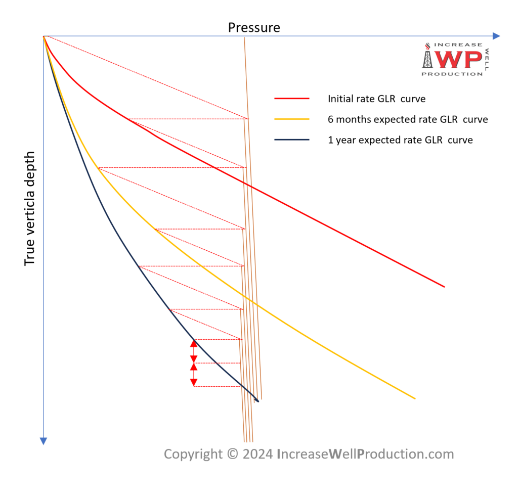
Figure 5: Gas lift design based on multiple liquid rate GLR curves
Conclusion
Achieving 2,500-plus bbl/d total fluid rates is well within the grasp of the High Rate Unconventional GLR-Based Method. Utilizing this system, 270-plus psi of drawdown (Figure 6) within several days has been seen following installation of lift. Based on data from an installed BHP gauge, accurate pressures have been tracked and production rates have reached volumes of more than 3,000 bbl/d. All this is from individual wellhead compression in the form of a three-stage 200-hp, gas-powered natural gas compressor with an operating discharge pressure of 1,250 psi.
Continued installations may be needed to gather more conclusive data regarding the broad application of this system. Higher rates can be achieved and fewer valves can be used. There is no need to limit the bottom valves to the tight 500-ft spacing based on the status quo or arbitrary existing practices.
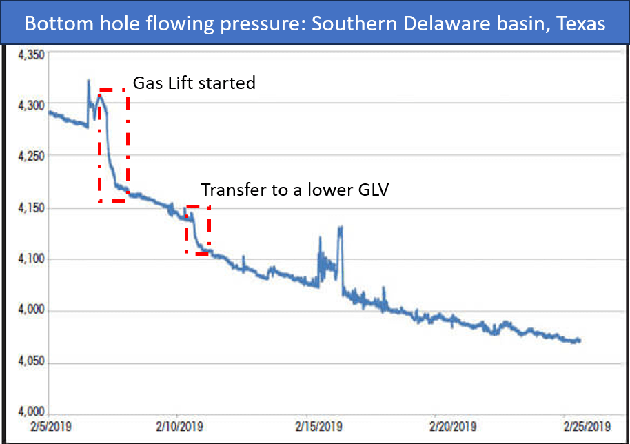
Figure 6: A consistent declining BHP from the lift process demonstrates an efficient gas-lift design. (Source: Concho Resources Inc.)


One Comment