Gas Lift Unloading Valve Bellows a key component often neglected that can kill the run life of your Gas Lift well
Introduction
The operating of a gas lift well relies primarily on the proper work of gas lift unloading valves. A key component of these gas lift valves is the bellow. Over the years a design has imposed itself and is currently used on almost every gas lift valves. This article will discuss gas lift valve bellow and respond to several questions including, what is a gas lift valve bellow, what is the function of a gas lift valve bellow, how to maximize the run life of a gas lift valve bellow. We will review the current design of gas lift valve bellow and see what innovative solutions are available on the market.
Fundamentals of the gas lift system
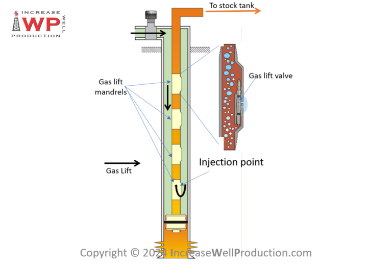
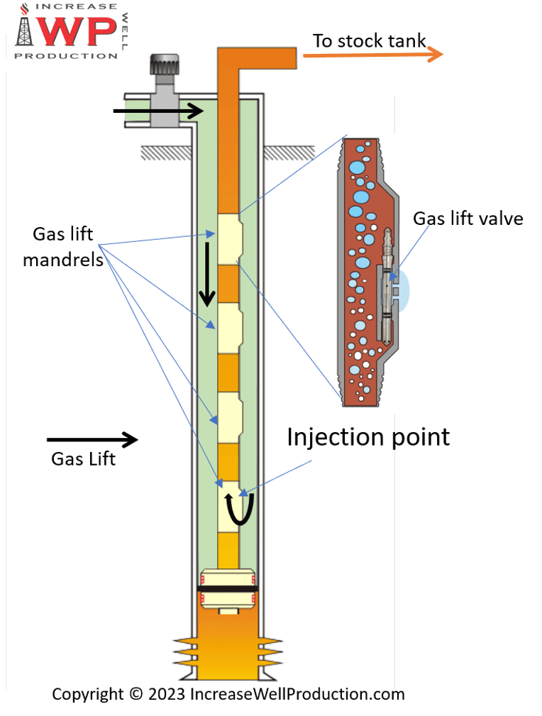
When operating a well in gas lift, gas lift will be injected from the casing to the tubing across gas lift valves. This injected gas will lighten the reservoir fluid and facilitate its flow to the surface. For a gas lift well to be optimized the gas lift should be injected only through the lowermost valve. That way the injected gas will lift the full height of the well and hence has a maximized efficiency.
The gas lift moves from the casing to the tubing across gas lift mandrels equipped with gas lift valves (figure 1). For this movement to be possible the pressure in the casing must be higher than the pressure in the tubing at the depth of the valve.
Gas Lift unloading sequence – the need for shallow gas lift valves
At the startup of a well, at the depth of the lower most valve, it is usually not the case. Hence the well must go through a starting up sequence, also known as the gas lift unloading sequence.
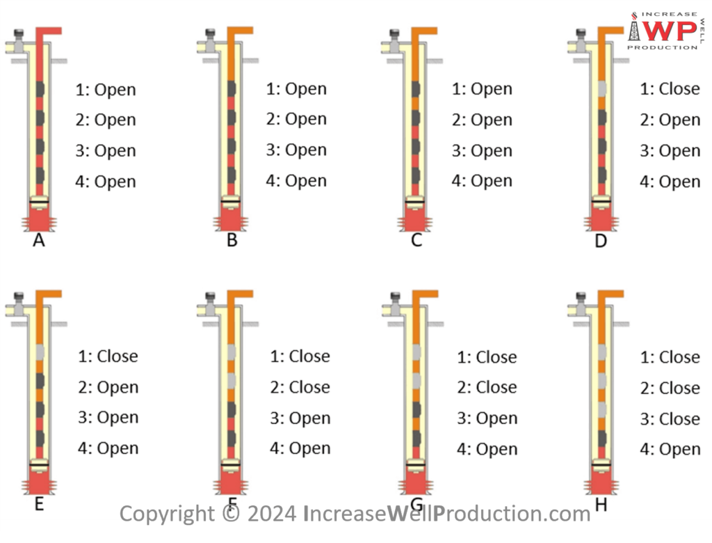
During this sequence gas lift will be injected initially through a gas lift valve higher in the tubing (hence where the tubing pressure is lower than the casing pressure) to initiate the well production. As the well starts to produce the fluid in the tubing above that first gas lift valve gets lighter (as it is now a mixture of formation fluid and injected gas) and drawdown is applied on the reservoir, hence the bottom hole flowing pressure decreases and so does the tubing pressure all along the tubing.
Gas lift injection point transfer to a lower valve
This decrease of pressure in the tubing allows the casing pressure at the depth of the 2nd valve to become higher than the tubing pressure and hence gas lift can flow across the 2nd valve. For the gas lift injection point to fully transfer from the 1st to the 2nd valve, the first valve must close. This closure will be triggered by the drop in the casing pressure. As gas lift is injected across both valves at the same time (from the casing to the tubing), the amount of gas stored in the casing decreases, hence the casing pressure decreases. Once the casing pressure goes below a certain value, the 1st gas lift valve will close, and the gas lift injection will have then fully transferred to the 2nd valve.
This gas lift injection transfer from the 1st to the 2nd gas lift valve, will repeat multiple times until the gas lift is injected across the lower most gas lift valve in the well (figure 2).
Gas Lift unloading valves function and working principle
For injecting gas lift across a gas lift valve it is also necessary that the valve is open. This opening is also regulated by the casing pressure that must reach a certain value for the valve to open.
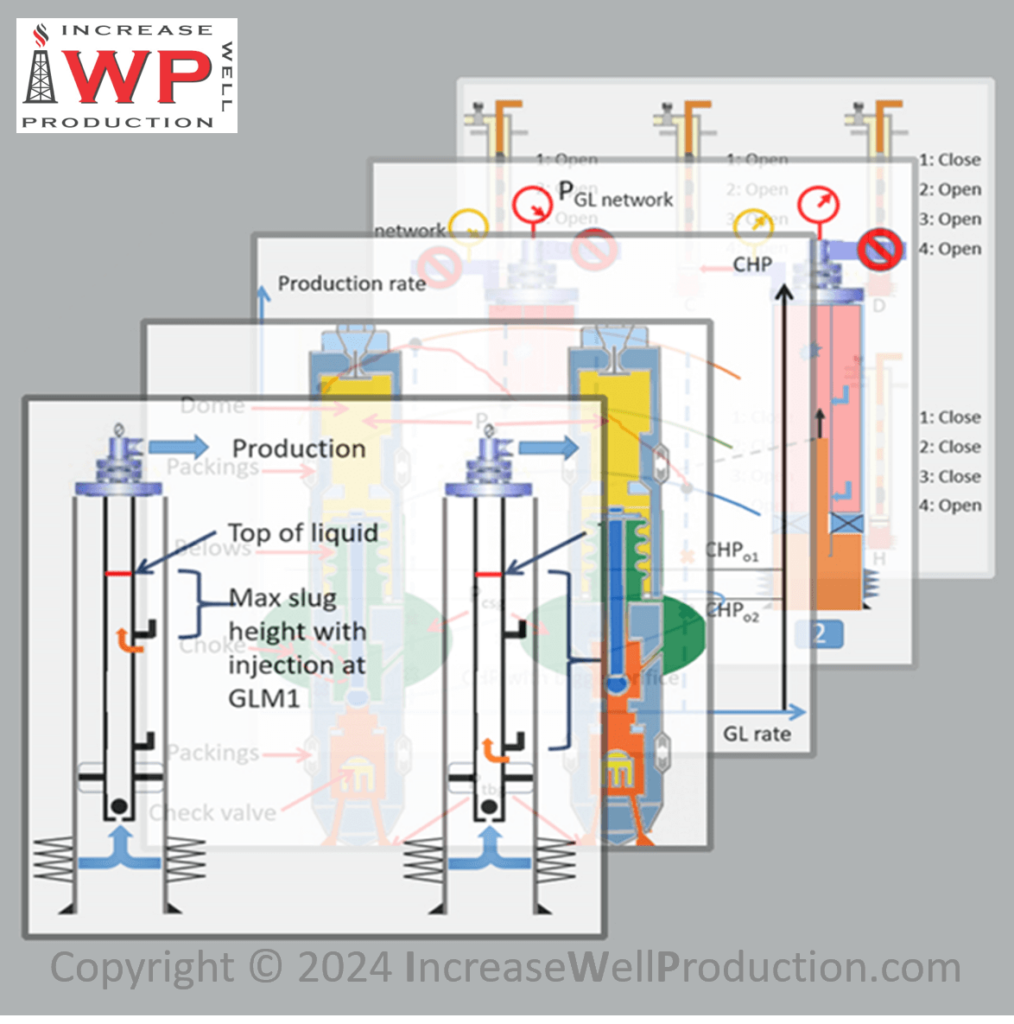
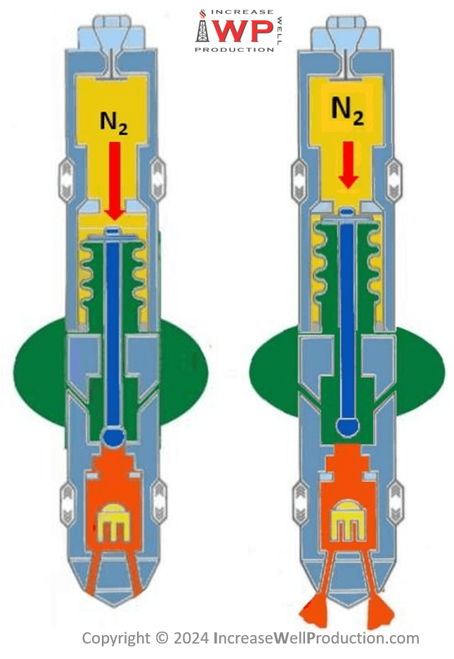
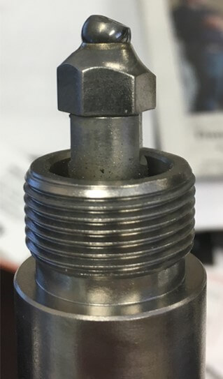
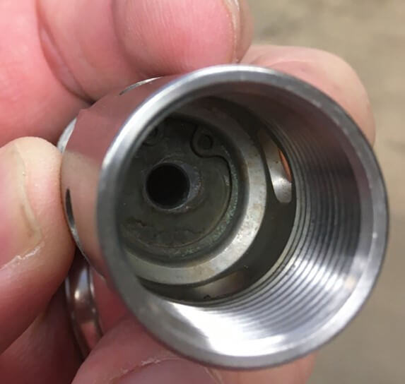
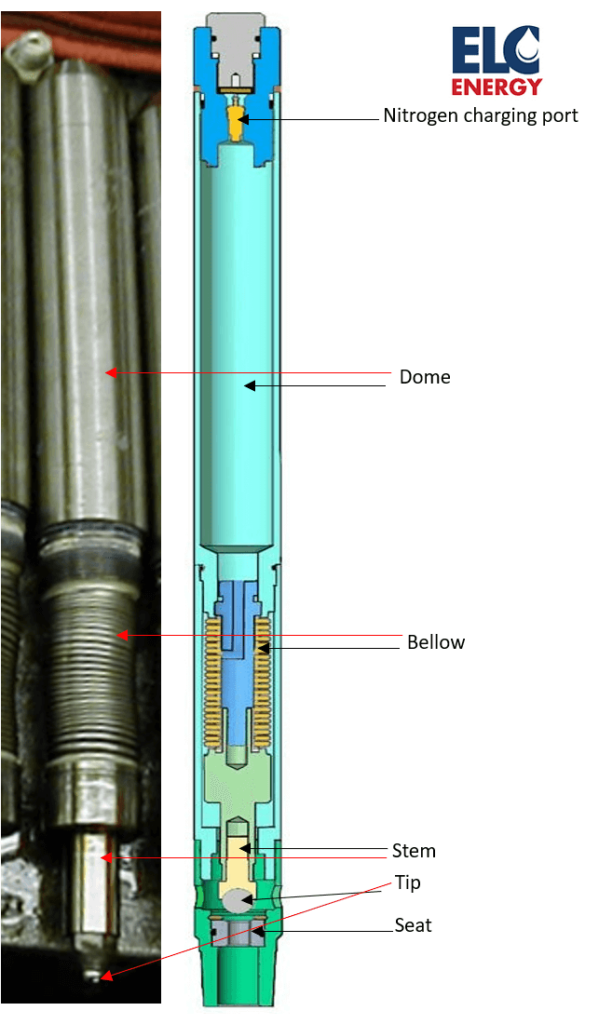
A gas lift valve opens by the vertical movement of a stem. In the closed position the tip (figure 4) of the stem rests on a seat (figure 5). As the casing pressure (or the gas lift injection pressure) increases and reaches the valve opening pressure, the stem will move upward creating a space between the tip and the seat (figure 3). The gas will then be able to flow across the valve moving from the casing to the tubing.
Hence we have seen that to perform the unloading sequence of a gas lift well, the well must be equipped with intermediary gas lift valve that will open at a certain gas lift injection pressure and close at another value. Valves are also equipped with a stem attached at its end that moves vertically to open and close the valve. These valves are called gas lift unloading valves.
Gas Lift valve bellow
To allow this unloading sequence, gas lift unloading valves are calibrated to open and close at the right gas lift injection pressure. The most common type of valve uses a chamber called the dome filled with nitrogen for this calibration. The higher the nitrogen pressure in the dome, the higher the gas lift opening (and closing) pressure. The nitrogen is kept segregated from the gas lift by a bellow (figure 6). The stem is attached to the bellow and the bellow will compress or expand as the stem moves up or down.
Gas lift valve operating range
Gas lift unloading valve typically need to operate at gas injection pressure from 800 to 1600 psi. Standard gas lift valves usually have a maximum operating pressure of 1800 psi, although high pressure gas lift unloading valves capable of sustaining a gas lift injection pressure of up to 10 000 psi exist.
The full travel of the stem varies slightly depending on the valve port (seat) size, but overall the value is around:
- 167 inch for 1 inch gas lift valves
- 287 inch for 1.5 inch gas lift valves
In terms of temperature rating, gas lift valves contain elastomer which is typically the component that creates the limit. Standard valves are rated for temperatures up to 250°F, while valves rated for up to 400°F are also available.
When installed in a well, a gas lift unloading valve is expected to work for multiple years, sometimes over a decade. It must therefore handle multiple cycles of opening and closing without failing.
Gas lift valve bellows must be designed to meet these operating conditions.
Featured courses


3-ply bellow
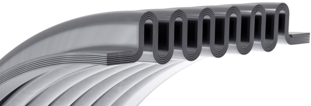
Gas lift valve bellows are typically made of several (usually 2 to 3) metal tubes layers (figure 7) called ply (hence 2-ply or 3-ply). Multiply bellows are preferred to one single thick ply bellows as they bring more flexibility (each thin sheet of metal will be more flexible than a thicker one) and higher pressure rating (multiple ply allows for a total thickness sufficient for targeted pressure rating).
It is also possible to select a different material for each ply which could allow to optimize the run life of the bellow (for instance the layer in contact with gas lift could be made of a material with higher corrosion resistance properties, while other layers could be made of a material that brings higher mechanical resistance). However, this technique is not used for gas lift unloading valve bellows which are typically made of Monel. The use of Inconel is also becoming more frequent for high pressure gas lift applications or in corrosive environments.
Gas lift bellows manufacturing process
A simplified process of gas lift valve bellow manufacturing will go through the following steps:
- Cutting of the tubes (that will form the plies).
- Draw processing of the tubes to bring them to their targeted wall thickness.
- Telescoping the tubes together. In 3-ply bellow, 3 tubes are telescoped together.
- Bulge and roll forming of the bellow. This is when the convolutions are created.
- Trimming the ends of the bellow. This is to only keep the part with the convolutions.
- Circle welding of the plies at both ends of the bellow.
- Leak testing and final inspection
Internally and externally pressurized bellows
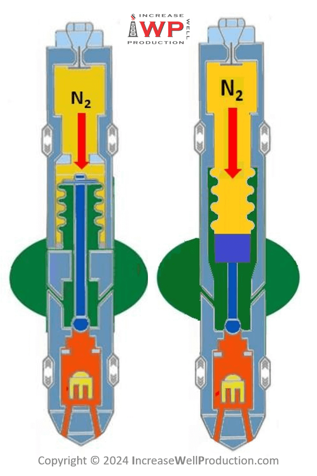
Bellows can either be internally or externally pressurized (Figure 8). Almost all gas lift unloading valves use internally pressurized bellow. It means that the nitrogen pressure is applied inside the bellow and will expand it so that the stem moves down, for the tip to reach the seat. To open the valve the bellow will be contracted by the gas lift pressure that will push it upward.
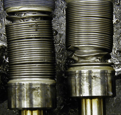
Bellow squirm and tilt
Internal dome-charged bellows are subject to instability. Squirm is a column instability and is defined as a gross lateral shift of a center section of the bellow, while the ends sections remain fixed. Tilt is an in-plane instability whereby convolutions become non-parallel to each other (figure 9).
Externally dome-charged bellows have a much higher stability than internally dome-charged bellow. This is due to the compression of the bellow that brings the convolutions closer together, hence supporting each other. Such bellow will therefore resist better over time to the opening and closing cycles of a gas lift valve. It is therefore surprising to see that almost all gas lift valves are currently manufactured using internally dome-charged bellows.
Gas lift valve bellow over-pressurization
A common failure mode of a bellow is when it gets over-pressurized. Indeed, as the gas lift pressure is applied on the bellow (shown by the oranges arrows in figure 10) at a value above the gas lift valve opening pressure, the bellow will compress, and the stem will move upward. If the gas lift pressure (or the pressure applied on the outer part of the bellow) increases further, at some point the stem will reach its maximum travel and won’t be able to move further upward. If the pressure applied on the outer part of the bellow increases further, then the bellow will deform plastically and ultimately collapse (figure 11).
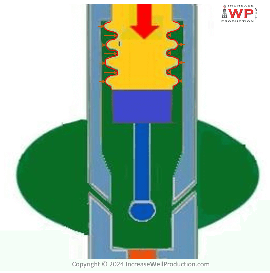
Silicon oil bellow protection from over-pressurization
Following the completion of a well, the tubing casing annulus is full of liquid, hence the pressure in the casing is very high at that time due to the hydrostatic pressure created by this liquid. Gas lift valves are therefore commonly exposed to over-pressurization and their bellow must be protected against that. This protection is achieved by filling partially the dome with silicon oil, so that the bellow is soaked in this incompressible liquid. As the stem reaches its maximum travel, it closes a “chamber”. By doing so it traps silicon oil and the bellow is entirely filled with this fluid. Hence as the fluid is incompressible, it will prevent the bellow from collapsing when the pressure on the other side of the bellow wall increases.
This is illustrated by the schematic here below (figure 12) made for an externally dome-pressured bellow. The gas lift injection pressure is represented in red, while the silicon oil appears in blue. As the stem reaches its maximum upward travel, a positive seal is activated, and silicon oil is trapped around the bellow. So, if the pressure in red increases further, the bellow won’t deform as it is surrounded by an incompressible fluid that won’t let it change shape.
This silicon oil also has the function of lubricating the bellow and therefore increases its run life.
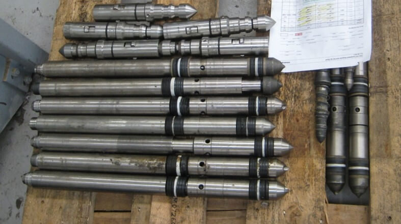
Gas lift unloading valve storage
Silicon oil is very viscous, hence if coming out of the bellow area (for instance after a long storage in the horizontal position), even when the gas lift valve is placed back to the vertical position, the silicone oil will not flow back to the bellow volume. To get the silicon oil back around the bellow, the valve must be heated for 30 minutes at 170 to 200°F and the valve must be worked to open and closed position several dozens of times.
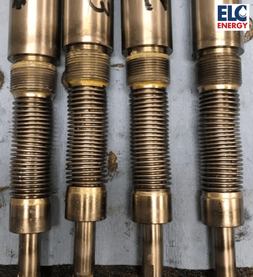
For that reason, gas lift unloading valves must be stored vertically with the dome facing up. It is rarely the case as storing the valve in a horizontal position (figure 13) is more convenient and most technicians are not aware of this silicon oil presence and function.
Limitation of the bellow protection through the use of silicon oil
While the silicon oil offers a fair protection for the bellow against over pressurization, it is not a perfect solution. Indeed, if the valve is installed in a deviated portion of the well, some nitrogen will remain trapped in the area that should be filed with silicon oil only. Hence the chamber is not entirely filed with incompressible fluid and the bellow will not be perfectly protected (figure 14).
It also appears that nitrogen tend to dissolve in the silicon oil making the mixture a compressible fluid. This was observed through test in laboratories where a chamber was filled with silicon oil pressurized with nitrogen. After releasing the pressure in that chamber, a “Coca Cola” effect was observed. Bubble of gas appeared in the silicon oil and accumulated at the nitrogen-oil interface to form foam.
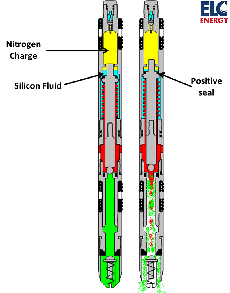
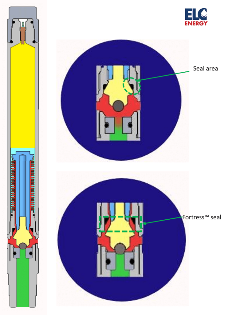
The Fortress™ seal
A solution to that problem was developed by Zlatko Salihbegovic from Z-Tech Design. The Fortress™ seal utilizes an innovative positive mechanical seal instead of relying on an incompressible fluid. As the stem moves up and reaches its maximum travel, a positive seal activates below the bellow and isolate it from the injection pressure (figure 15). Hence, if the injection pressure increases further, the bellow doesn’t get exposed to it and will not deform. This smart solution eliminates bellow failure by over pressurization and ensure a longer run life of gas lift unloading valve. Such valve is currently commercialized by ELC Energy.
Conclusions
Operators rarely investigate the failure mode of their gas lift valves. The main reason is probably the low cost of such equipment and the much longer run life achieved with gas lift compared to ESP. Yet performing systematic dismantle inspection failure analysis (DIFA) on pulled gas lift valves, would help to improve the design of such equipment.
Gas lift valve bellows seem to have been a neglected component in the design of gas lift unloading valves. While the current design has been functioning effectively with conventional gas lift applications, new forms of gas lift (high-pressure gas lift, gas lift in subsea and deep-water wells) require higher gas lift injection pressure and an improved design of the gas lift unloading valve and its bellow. Several gas lift valve manufacturing companies have already proposed some innovations like bellows made of Inconel, externally dome-charged bellow or the Fortress™ seal. Operators and gas lift valve manufacturers should consider focusing on this component to see how it could help improve the operating of their gas lift wells and hence increase the production of their wells.