This article was written by Zlatko Salihbegovic from Z Tech Design
Introduction – What is Gas Lift Valve ageing?
- Gas Lift Valve ageing process is being used in oil industry for 50-60 years. The purpose of ageing process is “to expose bellow to pressure significantly higher than max working pressure which will cause final bellow crimping/compression with intent to stabilize valve/bellow operating parameters, provide consistent valve performance as opening, closing pressure and valve load rate”. Ageing process permanently changes bellow convolution radiuses. Only convoluted/formed bellows are exposed to ageing process, edge welded bellows are not exposed to ageing process.
Gas Lift Valve ageing principle
- Ageing process is usually performed by applying 1000 PSI dome pressure and 5000 PSI water injection pressure, valve is opened and closed several times and ageing process might be repeated several times. Ageing process is performed by submerging valve in water in custom designed ageing chamber.
- Ageing process does not work as described/desired, and it is wrong process that should not be performed.
Effect of ageing on Gas Lift Valve bellow
- Bellows used in Gas Lift Valve are made from three 0.005” thick layers usually rated by manufacturers to 250 PSI working pressure. Material used is usually Monel 400, Inc 625 and 718.
- Being manufactured from very thin material bellows plastically deform every time when exposed to pressures differential larger than 500-600 PSI.
Featured courses

- During ageing process when 1000 PSI dome pressure is applied bellow convolution radiuses R changes depending on pressure orientation, external or internal. If pressure is internal, OD convolution radius R increases while ID radiuses decreases and vice versa. When 5000 PSI injection pressure is applied convolution radiuses change in opposite direction. Changes are severe. After ageing, 5000 PSI is released and now convolution deformation occur in opposite direction driven by 1000 PSI dome pressure. This is happening every time injection pressure is released to atmospheric pressure.
- Valve is shipped with no dome pressure and ageing process is usually repeated at well site where deformation explained above occurs again. When valve TROP-test rack opening pressure is being set, say to 2000 PSI, bellow is again plastically deformed.
What to avoid doing to your bellow
- For bellows to work properly and as designed bellow geometry must not be changed except bellow length from LF to LC during accurate crimping process. Bellow convolution radiuses must not be changed.
- Picture below shows bellow cross section exposed to 1000 PSI external pressure, note that ID convolution radiuses R are enlarged, while OD radiuses are reduced. Bellow convolution radiuses deforms plastically every time 500-600 PSI differential pressure is applied to below.

- Picture below shows convoluted/formed bellow typical dimensions.

- Typical dimensions for 1.5” nominal size bellow are shown below.
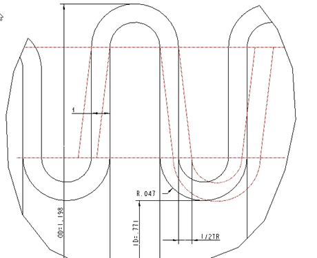
- Bellow travel-TR depends on t-wall thickness, bellow OD and ID, convolution radius R and material.
- During crimping and ageing process bellow dimensions must not change except bellow length from LF to LC. However, in most cases depending on type of crimping/ageing process used, bellow convolution radius R changes or/and convolution shape is completely deformed. This change of radius and shape changes/reduces bellow allowable travel TR and in application convolutions are exposed to plastic deformations resulting in bellow premature failures due to the fatigue. In Gas Lift Valve application bellow must never be compressed to length shorter than LC.
The worst gas lift valve in the business:
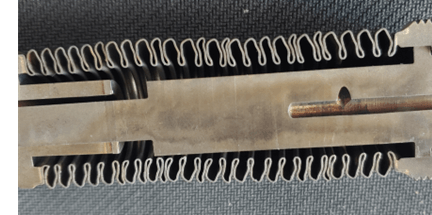
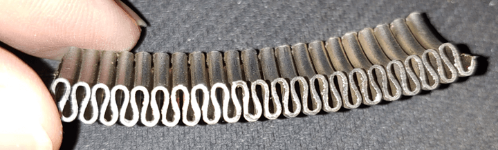
- The picture bellow shows cross section of a Gas Lift Valve. This is very first Gas Lift Valve design, note horrible shape of bellow convolutions. This Gas Lift Valve is first soldered against mating parts in free length L, crimped usually using external pressure and then aged. Picture is worth more than thousand words. Everything that could be wrong went wrong with this design. Unfortunately, this is the best selling Gas Lift Valve in the business.
- Interestingly, although valve aging process is used for 50-60 years there is patent # US 2021/0246769A1 issued for bellow ageing process, I am not sure how this was possible. This patent describes ageing process performed with air pressure. This patent is good example how not to age a Gas Lift Valve and bellow. No one is ageing Gas Lift Valve with air but water to avoid explosive decompression problems.
Featured courses
So, what is the solution?
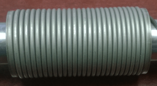
- First step is proper bellow crimping where only bellow length LF is changed to LC as per manufacturer recommendation. Proper bellow crimping must result in crimped bellow where it is essential to maintain bellow radiuses. My pending patent # 17/108,491 produces perfectly crimped bellows, see picture of bellow cross section below. Note perfectly formed bellow convolution Ω-omega shape.
- Picture below shows perfectly crimped bellow per my pending patent # 17/108,491 using custom designed crimping device. Note that bellow is crimped as self standing, not soldered against mating parts.
- Second, by design, Gas Lift Valve bellow should never be exposed to differential pressure higher than manufacturer recommended working pressure, usually 250 PSI for formed bellows.
- Today, there is no Gas Lift Valve on the market that meet this criteria.
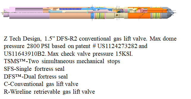
Introducing game changer: Gas Lift Valve with dual Fortress™ seals per my patent # US11242732.
- Dual Fortress™ seal Gas Lift Valve features formed bellow that is never exposed to differential pressure higher than 200 PSI.
- Bellow in this Gas Lift Valve is completely protected from high injection and dome pressure by Fortress™ seals.
- Bellow in this valve is crimped per my pending patent # 17/108,491 resulting in perfectly crimped bellow.
- This Gas Lift Valve can be exposed to 15 KSI injection pressure without any danger for bellow.
- This Gas Lift Valve features spring loaded telescoping stem, which is complex, however applying my patent # US 11643910 B2-”Gas Lift Valve with two simultaneous mechanical stops” telescoping stem is not needed and is eliminated from design resulting in simpler and more reliable design.
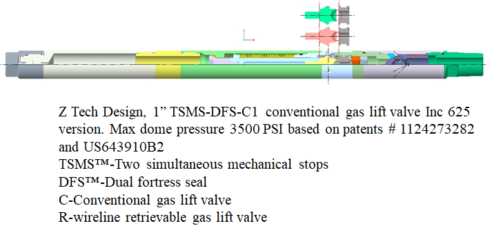
- This gas lift valve is not aged, this is wrong and unnecessary procedure. Valve is prepared for use by applying max dome pressure of 3500 PSI depending on bellow material used.
- Drawing below shows a Gas Lift Valve with dual Fortress™ design with applied two simultaneous mechanical stops.
Next:


One Comment