Written by Mina Atta, Field Engineer at Tam Oilfield Services, in collaboration with Damien Leonard, Founder of Increase Well Production Limited.
Introduction
Penetrators are among the most critical components in Electrical Submersible Pump (ESP) systems. They provide a safe electrical pathway that powers the downhole pump while maintaining well integrity and safety under harsh operating conditions.
Beyond electrical transmission, penetrators play a vital role in the well barrier system, ensuring isolation between different pressure zones and contributing directly to overall well integrity.
This article combines engineering fundamentals with field experience to provide practical insights into penetrator design, selection, and real-world applications in oil and gas wells.
What is a penetrator in ESP applications
A penetrator is a specialized sealing device designed to allow the passage of electrical cables through pressure-containing barriers in the well system, while maintaining pressure integrity and electrical insulation.
In ESP applications, penetrators ensure safe power transmission from surface to downhole equipment without compromising well integrity. They are also commonly called feed-through.
Types of Penetrators in ESP Systems
In ESP applications, penetrators are classified into two types:
A) Wellhead Penetrators
B) Packer Penetrators
Each type serves a specific function within the completion design while ensuring both electrical continuity and mechanical integrity.
Featured courses

(A) Wellhead Penetrator:
The wellhead penetrator enables the ESP power cable to pass through the tubing hanger while maintaining the wellhead system’s pressure integrity and ensuring reliable electrical insulation.
It is designed to:
- Withstand high wellhead pressures without leakage
- Provide excellent electrical insulation to prevent short circuits
- Resist high temperatures, H₂S, and corrosive fluids
- Ensure long-term operational reliability
Overview of the wellhead feed-through system architecture
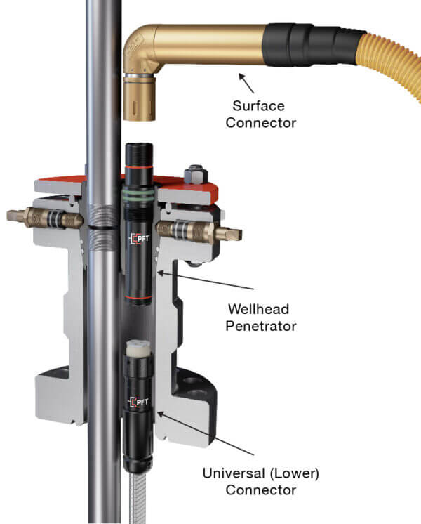
Figure 1
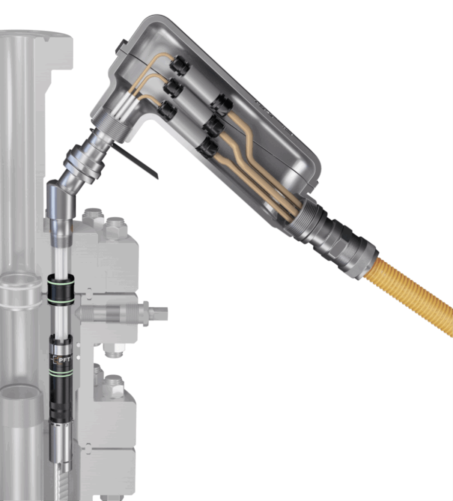
Figure 2
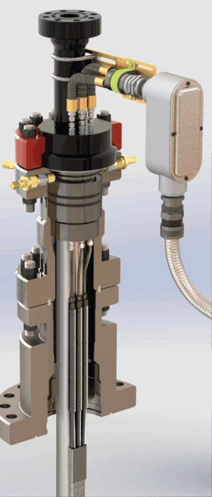
Figure 3
Source of illustrations: https://pftsys.com/
Figure 1: Mandrel type modular wellhead penetrator
Description: A high-pressure, 3-component mandrel system featuring a surface connector, a central pressure-block mandrel, and a universal lower connector. It utilizes high-performance thermoplastic insulators (such as PEEK) to ensure a gas-tight seal.
This modular design provides a positive barrier against gas migration. Unlike older epoxy-filled systems, this mechanical-seal approach can handle higher pressures (up to 5000 psi) and helps prevent explosive decompression in high gas-oil ratio (GOR) wells.
Figure 2: Splice-free wellhead penetrator
Description: A cross-sectional view of a field-attachable termination where the ESP cable is integrated directly into the connector using mechanical compression seals for each individual phase.
Key benefits: The core advantage is operational flexibility. This system allows engineers to adjust cable lengths on-site. By eliminating the need for a splice between the lower connector and the main power cable, this system significantly reduces rig time and potential failure points associated with this operation.
Figure 3: Phase-separated penetrator
Description: An integrated surface assembly that provides a shielded pathway for power delivery, featuring a corrosion-resistant junction housing designed for hazardous area classifications. In this configuration, each phase runs in its own dedicated bore through the tubing hanger.
Key benefits: This configuration prioritizes mechanical robustness and environmental isolation. It protects the electrical terminations from vibration and atmospheric corrosion, ensuring that the electrical integrity of the entire barrier system is maintained from the surface down to the wellbore. It also features improved thermal dissipation and is the preferred setup when clearance in the annular space is restricted.
Actual field installation of wellhead penetrators
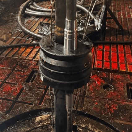
Figure 4: Tubing hanger with lower connector
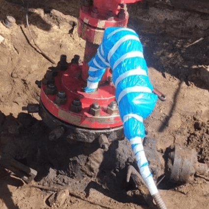
Figure 5: Wellhead with upper connector, junction box type
(B) Packer Penetrator:
When ESP cables pass through a packer, the packer penetrator becomes essential.
It is engineered to:
- Allow safe passage of ESP power cables through the packer with uninterrupted electrical continuity of the ESP system
- Preserve the mechanical integrity of the packer barrier while enabling safe cable penetration and withstanding high differential pressures across the packer
- Ensure long-term reliability in high-pressure, high-temperature wells
Overview of the Packer Penetrator system architecture
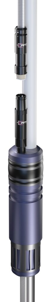
Figure 6: C-PAK Packer Penetrator Field Attachable by PFT
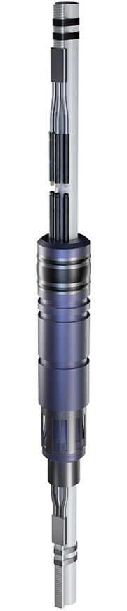
Figure 7: Tri-Gator Packer Penetrator Field Attachable by PFT
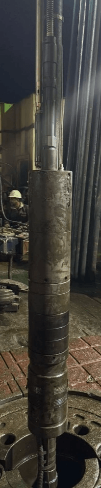
Figure 8: Packer penetrator mandel type
Figure 6: Mandrel-type packer penetrator
Description: Like for wellhead penetrators, packer feed through can be achieved with a large single bore across the packer. Such a system may require cable splicing above and below the packer, while some manufacturers offer a no-splice option, as in the system shown in this illustration.
Figure 7: Phase-separated packer penetrator
Description: Here again, the packer feedthrough is achieved in a similar manner to that of the wellhead penetrator. The featured system requires a separate bore in the packer to route through each phase of the ESP power cable. No-splice option is offered by certain suppliers, as in the system shown on this illustration. This solution is preferred when the annular space is a constraint.
Featured courses

Criticality of penetrators in ESP operations
Penetrator performance directly impacts the overall reliability and integrity of ESP systems. Failure of the penetrator may result in electrical system malfunction, loss of well integrity, fluid or gas leakage, and unplanned production downtime.
Conversely, proper design, selection, and installation of penetrators contribute to enhanced operational safety, improved production continuity, extended equipment lifespan, and better cost efficiency.
In one field case, penetrator failure due to loss of sealing integrity resulted in fluid ingress and subsequent electrical short circuit, leading to an unplanned ESP shutdown. The failed penetrator had to be replaced, resulting in the mobilization of a workover unit offshore for a cost exceeding one million dollars.
ESP Penetrator Design Considerations
Penetrator systems vary in design and installation methodology across oil fields. Therefore, proper selection and accurate installation are essential. Key factors include:
- Pressure and Temperature Conditions:
Penetrators are designed with a range of pressure and temperature ratings to accommodate various wellbore environments. Standard configurations support pressures between 3,000 and 5,000 psi, while specialized designs can reach up to 7,500 psi.
For High-Pressure High-Temperature (HPHT) applications, advanced systems may exceed 10,000 psi, with thermal capabilities reaching 450°F (≈232°C), depending on design and operating conditions. - Electrical Isolation Requirements :
To ensure safe and reliable power transmission, penetrators must comply with strict electrical isolation standards and maintain high dielectric strength. System voltage ratings range from 3 kV to 15 kV or higher, depending on the requirement of the ESP motor and system configuration. This ensures effective insulation and prevents electrical leakage or breakdown under harsh downhole conditions. - Amperage rating:
Penetrator electrical performance is commonly defined by current (amperage) rating, representing the maximum current-carrying capacity of the system. Typical industry ratings vary depending on design and application and may include values such as 140A, 160A, 180A, 190A, 215A, and up to 285A for high-capacity configurations. This rating is selected based on ESP motor requirements, conductor size, and insulation capability to ensure safe and reliable power transmission. - Corrosive Environment Resistance:
Material selection and sealing design are the primary factors in determining suitability for sour service (H₂S) applications. For standard service, materials such as Stainless Steel 316 or high-grade Carbon Steel with protective coatings are used to provide adequate corrosion resistance.
In contrast, sour service applications require Corrosion-Resistant Alloys (CRAs) such as Inconel 718 or Incoloy 825. These materials are designed to resist Sulfide Stress Cracking (SSC) and H₂S-induced corrosion, ensuring mechanical integrity, sealing performance, and long-term reliability in aggressive downhole environments - Installation quality and system reliability:
Installation quality and system reliability are ensured through controlled engineering practices and comprehensive performance verification, including electrical and pressure testing.
- Installation duration:
Installation duration varies depending on the penetrator design and system type available in the market.
Field-attachable, aka no-splice, systems generally offer faster deployment than factory-assembled units, which typically require additional on-site electrical connections, such as cable splicing, resulting in longer installation time. These systems are widely available in the market and include configurations such as Gator Feed, Tri-Gator, and C-PAK, among others.
Overall, system selection and configuration play a key role in balancing operational efficiency and reliability requirements in ESP applications.
Conclusion
Penetrators in ESP systems are critical enablers of well integrity, safety, and reliable production.
Their function extends beyond electrical connection to include pressure containment, barrier integrity, and long-term operational stability.
Ultimately, system reliability depends on proper engineering design, correct selection, and precise installation aligned with real well conditions.

Featured courses
ESP Intakes, Gas Separators and Gas Handling Solutions
500€